SSTB.
Spherical Superconducting Torsion Balance
Contact C. C. Speake
Over the last decade the Gravitation group at the University of Birmingham has been developing a new type of torsion balance1,2 for weak force physics. The instrument replaces the traditional torsion fibre with a magnetic suspension that utilises the Meissner effect exhibited by superconductors. A first generation instrument is currently being used to search for a possible interaction coupling quantum mechanical spin and ordinary unpolarised matter. Over the last 3 years we have been working on the development of a second generation instrument which will be used for a precision measurement of the Casimir force at cryogenic temperatures.
Mk I Instrument Description.
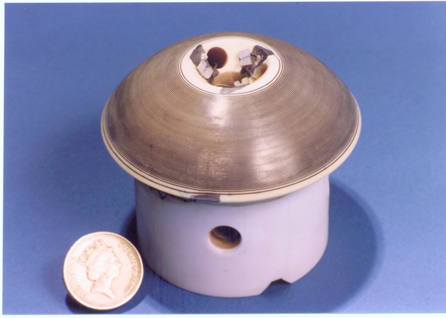
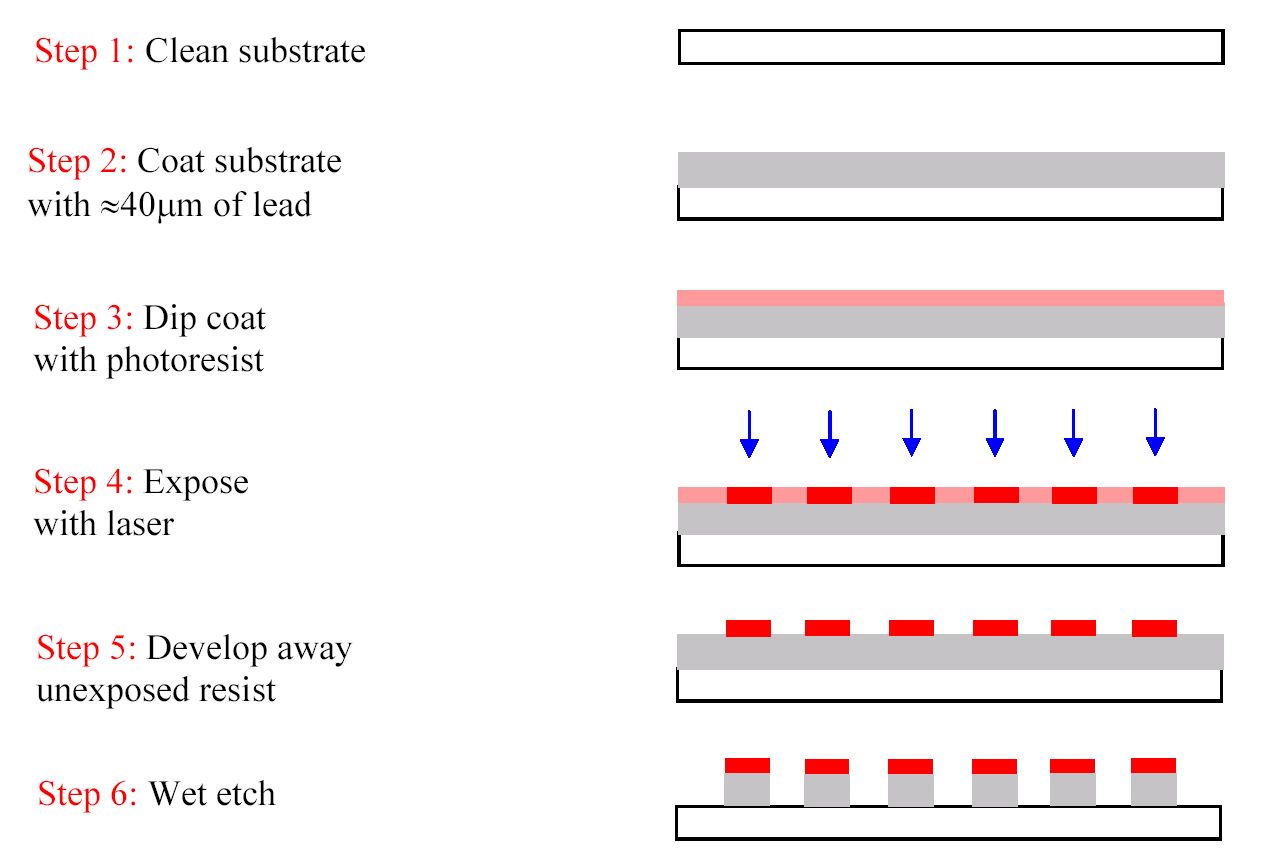
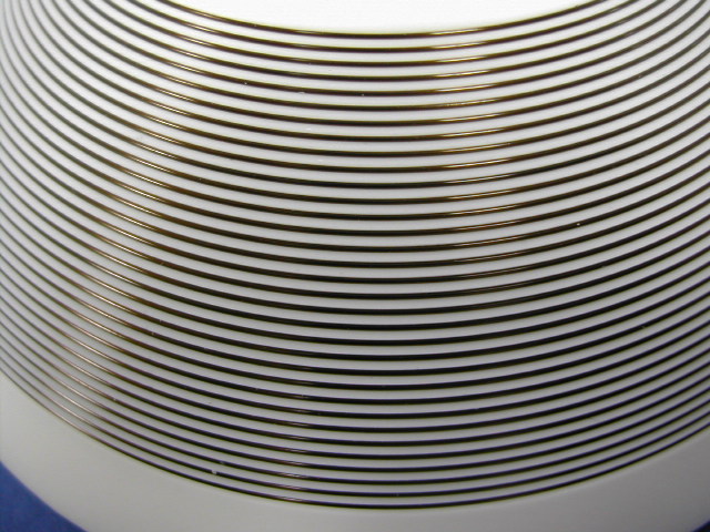
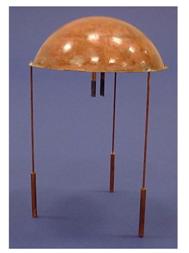
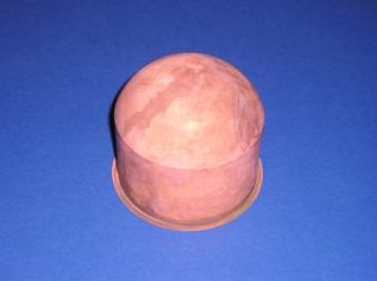
The Mk I instrument comprises a levitation bearing whose spherical surface is patterned with a coil and a float whose inner spherical surface is coated with lead (Pb). A photograph of the levitation bearing is shown in figure 1. The bearing is machined from a monolithic MACOR (a machinable ceramic) substrate. The spherical portion of the bearing has a radius of 42.9mm and a measured sphericity of better than 10um. The cylindrical portion of the bearing contains four holes whose centres are coincident with the centre of figure of the spherical surface. The holes locate coils that are used for the rotation detector. The levitation coil is fabricated with a photolithography procedure3 that is briefly described in figure 2. Initially a lead coat of approximate thickness 40 mm is thermally evaporated onto the clean substrate surface. A negative photoresist is then applied to the lead coat with a dip coating procedure. The coil is drawn into the photoresist using a He-Cd (442nm) laser with an approximate power of 6.5mW. After development of the unexposed photoresist we are left with a continuous metal coat and a photoresist coil. The final step involves a wet etch in copper (II) chloride. The critical current of the levitation bearing has been measured to be approximately 4.5A and results in a total lift capacity of the suspension of approximately 25g. Although the integrated thermal expansion of MACOR and lead are significantly different the coil has been successfully cycled to 4.2K in excess of 50 times without any noticeable degradation.
[Figure 1. Photograph of the levitation bearing showing the coil patterned onto the spherical surface and one of the holes that are used for the rotation detector.]
[Figure 2. Photolithographic
manufacture of the levitation bearing]
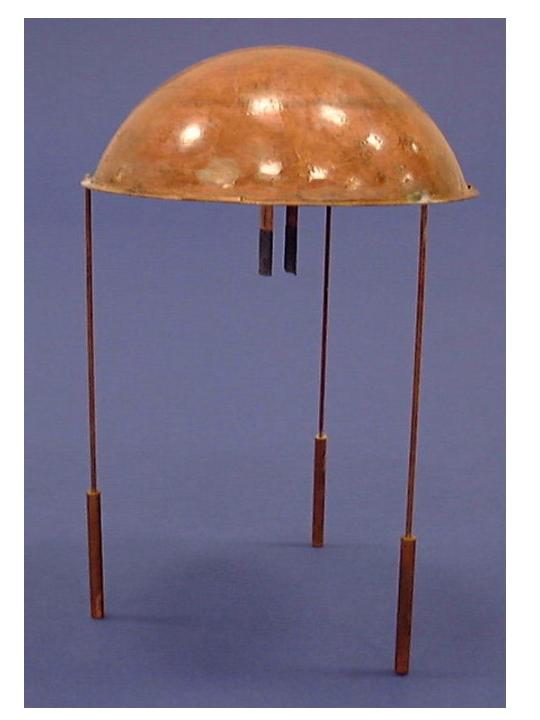
The float is shown in figure 3 and comprises three main components: (i) a spherical shell whose inner surface is coated with lead. The shell has an inner radius of 43.6mm and extends to a polar angle of 700 (ii) a central tube attached to the underside of the spherical shell (iii) a three-fold test mass geometry. The shell is fabricated by electroplating approximately 100mm of copper (Cu) onto the surface of an aluminium (Al) mandrel. The mandrel is then dissolved in a strong solution of potassium hydroxide leaving the electroformed copper shell. The sphericity of the uncoated mandrel has been measured to be better than 10mm. In addition to the high degree of sphericity that can be achieved on the inner surface of the float it is also believed that the shell is reasonably free of mechanical stress and should therefore cool without significant warping. The inner surface is coated with approximately 20mm of lead by thermal evaporation. The central tube is fabricated by electroplating 100mm of copper onto a cylindrical aluminium mandrel that is later dissolved. The tube is split into two quadrants whose lower 10mm are coated with a thickness of approximately 20um of lead. These coated quadrants form the part of the rotation detector described which is described later. Three long thin rods are used to support the test masses. The rods are fabricated from Oxygen Free High Conductivity (OFHC) copper and have dimensions f2mm x 100mm (diameter x length). The test masses are 1.9g OFHC copper cylinders of dimensions f3mm x 30mm. The float has a total mass of 18g, a moment of inertia of approximately 2x10⁻⁵kgm2 and a centre of gravity which is approximately 5mm below the centre of figure of the spherical shell.
[Figure 3. Photograph of the float showing the electroformed spherical shell, the three test masses and the central tube]
Mk II Instrument Description.
The major difference between the first and second generation instruments is the use of niobium (Nb) rather than lead as the superconductor. This choice is driven by the fact that the critical current of niobium is three times that of lead and that niobium is a more resilient material. Thus for identical cross-section superconductors the lift capacity should be nine times greater for a niobium suspension. This allows both the float to be made significantly more rigid and to operate well below any critical magnetic field. We are also taking care in the Mk II instrument to shield the levitation field from the rest of the instrument (i.e. rotation detector).
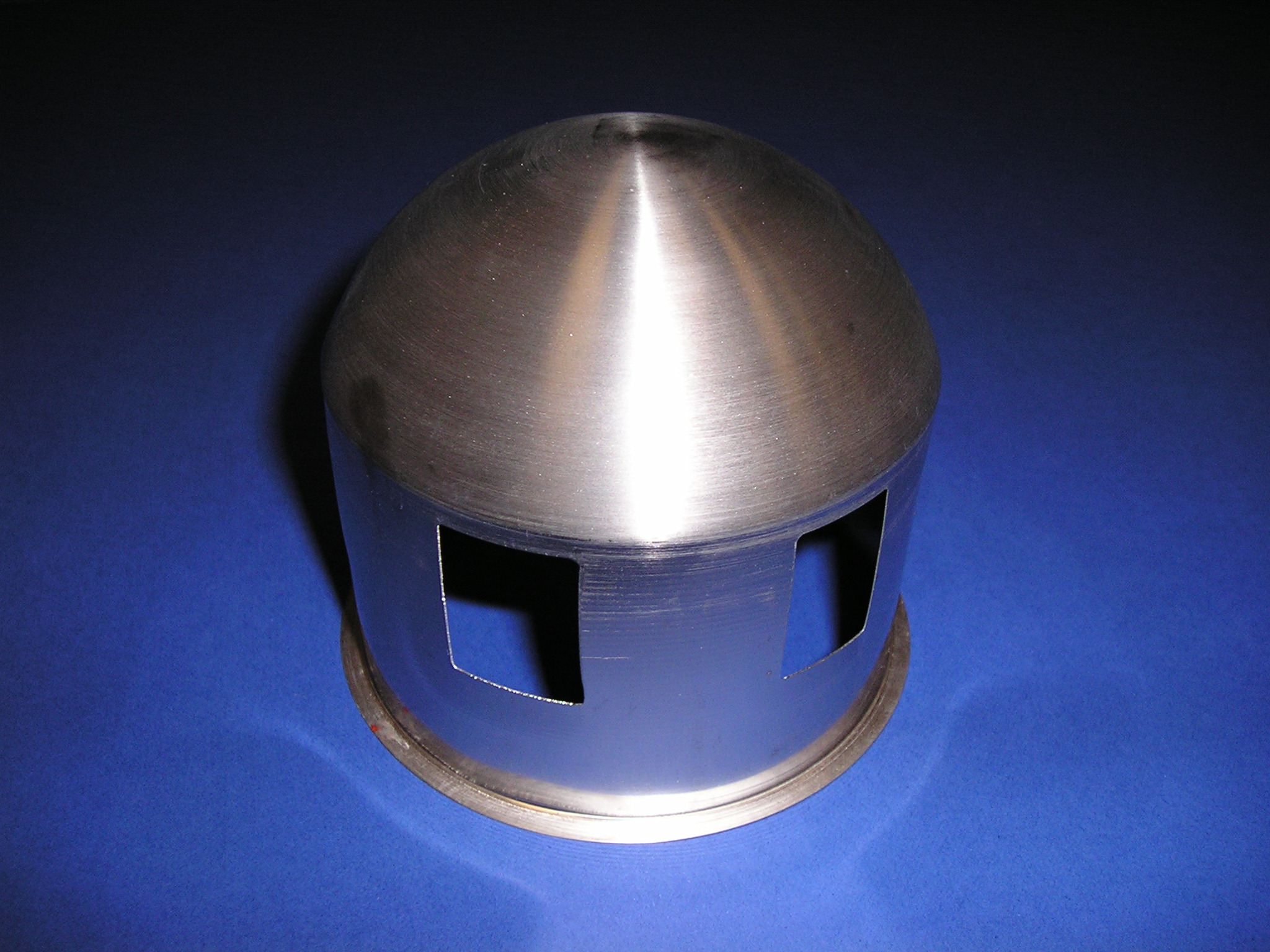
The levitation bearing is shown in figure 4 and is machined from a monolithic substrate of MACOR. A spiral groove is cut into the spherical surface of the bearing with a 3-axis CNC milling machine. The groove is filled with 0.25mm diameter hard-drawn niobium wire which is wound into the groove by hand (see figure 4b for a close-up view). The total length of the wire is approximately 10m and takes approximately 5 minutes to wind with a purpose built coil winder. The superconducting transition temperature of Niobium is 9.2K and the predicted critical current of the bearing is approximately 45A at liquid helium temperatures (4.2K). We have cycled the bearing to liquid helium temperatures several times without problems.

[Figure 4. (a) Photograph of the levitation bearing (b)Close-up
of the bearing showing the Niobium wire]
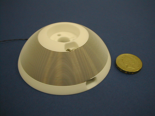
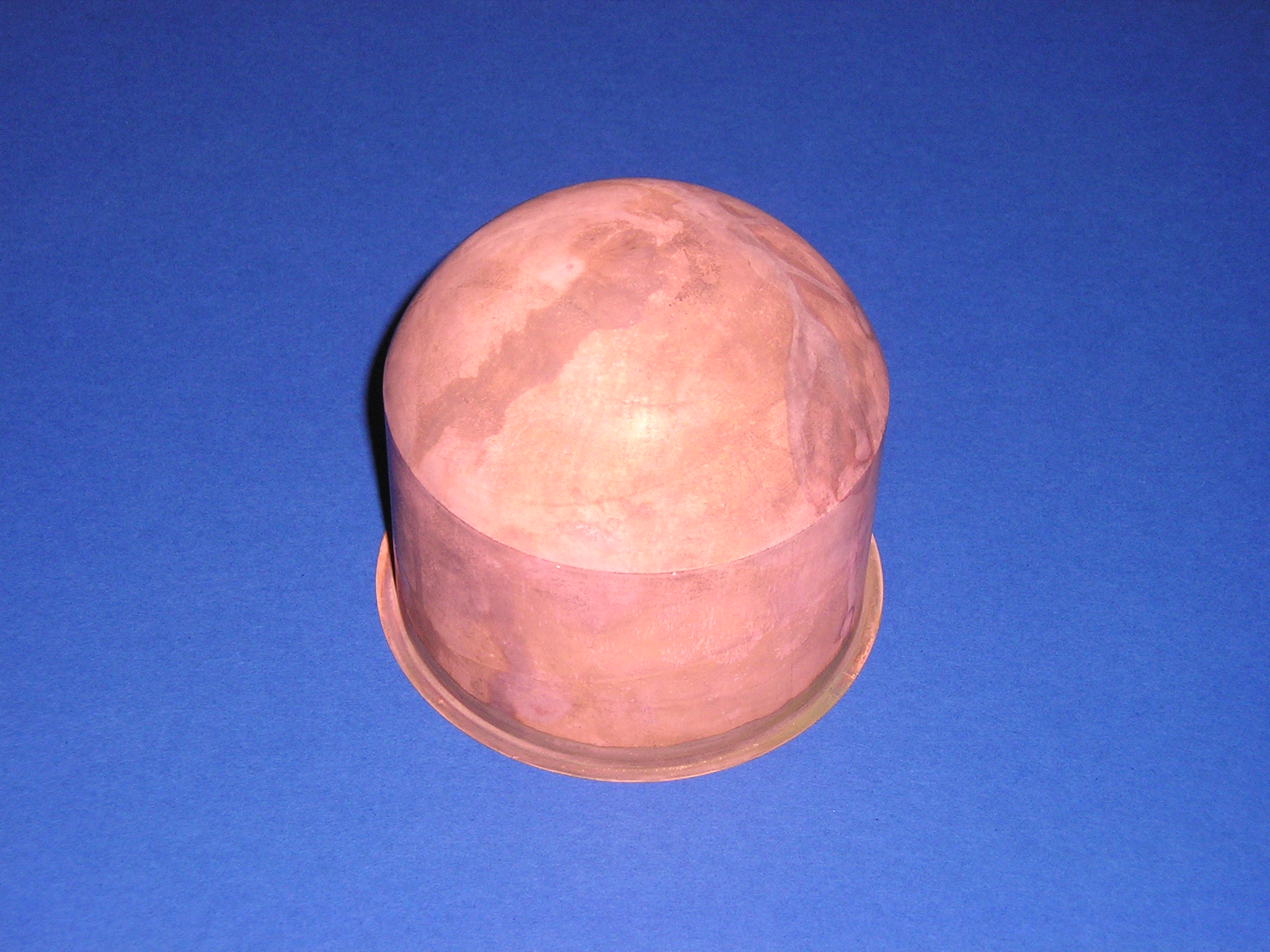
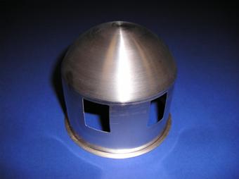
The float is currently being fabricated by two separate methods. The first (shown in figure 5) involves deep drawing it from a 0.2mm thick Niobium sheet by Plansee metals of Austria. The total mass of the float shell is approximately 50g and has a centre of gravity 10mm above the centre of the figure of the spherical shell. In order to produce a stable levitated object a mass ring is placed around the cylindrical portion of the float. The current float has a total mass of 100g and a centre of gravity 10mm below the centre of figure. This is still quite a conservative effective pendulum length and we plan to reduce the mass of the ring until this is 5mm. The benefit of operating with a small effective pendulum length means a reduced sensitivity to horizontal ground accelerations. The second method of fabrication is identical to the Mk I instrument. An aluminium mandrel is electroplated with approximately 0.2mm of copper. The mandrel is then dissolved with a strong solution of potassium hydroxide to leave the final shape (shown in figure 6). We currently have two of these copper shells. We plan to coat the first with lead to start initial experiments. In the meantime we will send the second shell to the PTB in Germany and have it sputter coated with Niobium. We can then characterise the performance of both of these superconducting materials.
[Figure 5. Photograph of the Niobium float]
[Figure 6. Electroformed copper shell]
Rotation Detector.
In the absence of trapped magnetic flux in the superconductors and imperfections in the manufacture of the bearing and float the torsion balance would have no preferred equilibrium position. We need to define a natural stiffness for the torsion balance and this is achieved with the rotation detector. The operating principle of the detector utilises inductance modulation of pairs of coils as the float rotates. With suitable superconducting circuitry, this inductance modulation can be converted into a current modulation that can be sensed by a SQUID magnetometer. The back action of the current in the circuit also provides the magnetic stiffness that defines the period of the torsion balance. The superconducting circuitry is shown in figure 7. Coil pairs L11/L12 and L21/L22 are connected in a series combination as a rotation of the float causes a similar inductance modulation in each pair. Heatswitches HS1 and HS2 are used to store persistent currents in the superconducting circuitry. The heatswitches comprise a section of superconducting wire that is non-inductively wound onto a copper post to improve heat sinking to the liquid helium bath. A small portion of the wire is wrapped with constantan wire to form the heater element. Flux transformer FT1 is used to couple external currents into the rotation detector circuitry for the purpose of applying external torques onto the float for servo control.
It is convenient to parametrise the inductance of the coils about the nominal zero position of the detector for the purpose of calculating the output sensitivity and stiffness of the circuit
 (1)
(1)
where L1 and L2 are the series combination of the coils pairs, f is the azimuthal angle of the float, ¶L/¶f is the gradient of the inductance and ¶2L/¶f2 is the curvature.
[Figure 7.Superconducting circuitry used to convert an inductance modulation of the pick-up coils into a current modulation in the SQUID]
An analysis of the circuit may be performed by writing down conditions for the total flux stored in the superconducting loops of the circuit and current conservation. It can be shown that the output current, to first order in angle, is given by
 (2)
(2)
and the flux coupled to the SQUID is,
 (3)
(3)
where i0 is the current that is initially stored in the circuit. The magnetic stiffness can be derived from the second derivative of the total magnetic energy stored in the circuit:
 (4)
(4)
References.
(1) C.C. Speake, G.D. Hammond, C. Trenkel, G.K. Rochester, T.J. Sumner, Meas. Sci. Technol., 10, (1999), 435
(2) G.D. Hammond, A. Pulido-Paton, C.C. Speake, C. Trenkel, Rev. Sci. Instr., 75, (2004), 955
(3) C. Trenkel, G.D. Hammond, C.C. Speake, Precis. Eng., 24, (2000), 139