Precision Measurement of the Casimir Force.
Contact C. C. Speake
Theory
In 1948 Henrik Casimir1 predicted that two perfectly smooth, infinitely conductive plates in a vacuum at 0K should feel an attractive force towards one another. The Casimir force is a macroscopic manifestation of quantum mechanics and quantum zero point energy.
In the quantum vacuum although the field can have zero value, the expectation value can be non-zero. The net result is that each electromagnetic field mode has associated with it zero point energy of 1/2ħw. The presence of the plates impose boundary conditions on these field modes and only those modes which have an integer number of half wavelengths fitting between the plates are resonant (see for example figure 1). Inside the cavity the resonant modes are enhanced, while outside the cavity all modes can be present up to, say, some suitable cut-off in frequency (in principle this could be the Planck frequency but in reality the mirrors become transparent before this limit is reached). The net result is that there is a radiation pressure pushing the mirrors together and this is the Casimir force2.
If the area of the plates is S and their separation is, a, the force can be written as,
 (1)
(1)
[Figure 1. Schematic of a cavity that is resonant for modes whose half wavelength is an integer of the plate spacing]
Since Casimir's prediction over 50 years ago there has been a large amount of theoretical work in fields where the Casimir effect can play an important role (see for example 3).
- Cosmological constant and dark energy.
- Quantum Chromodynamics and the bag model of hadrons
- Kaluza-Klein Theories and compactification of dimensions
- Mathematical Physics and Renormalisation techniques
- Quantum Field Theory and calculations of the Casimir force in non-parallel plate geometries (Proximity Force Theorem)
- Condensed Matter Physics and the inclusion of finite corrections
Over the last 7 years experimental interest in the Casimir force has been revitalised by the work of several groups. Indeed experimental studies into the Casimir Force offer a unique way of studying the Quantum Vacuum. In practice the geometry adopted by these groups departs from the original parallel plate geometry proposed by Casimir. The main reason for this is due to the problems associated with keeping plates parallel while separated by a few microns gap. As a result the typical geometries that have been used are sphere-plane4,5,6,7 and cylinder-cylinder8. The force in the sphere-plane geometry is modified (approximately) from equation (1) by the Proximity Force Theorem and is given by
 (2)
(2)
It is important to realise that the actual force that is measured can deviate significantly from the theoretical expressions given in equations 1 and 2. There are three main corrections that have to be included9. The first results from the fact that above the plasma frequency of the metal (roughly 1014Hz for gold) the mirrors become transparent. Thus as the separation of the mirrors is reduced the frequency of the bounded modes approached the plasma frequency and the measured force will reduce (i.e. the mirrors become transparent). At a gap of 100nm with gold coated mirrors the force reduces by roughly 50% of what is expected. The second correction is the surface roughness which is important due to the highly non-linear nature of the Casimir force. At a separation of 100nm and with a surface roughness of 10nm the force is increased by approximately 10%. Finally, measurements are not made at 0K and this results in the fact that thermal photons can also produce a net radiation pressure. In recent years there has been significant interest in the relationship between the corrections and how, for example, thermal and roughness corrections are coupled .
Birmingham Experiment
Over the last decade the Gravitation group at the University of Birmingham has been developing a new torsion balance for weak force physics. A description of the Mk II Superconducting Torsion Balance that will be used for the Casimir experiment has been given in a previous section.
Cryostat
Insert
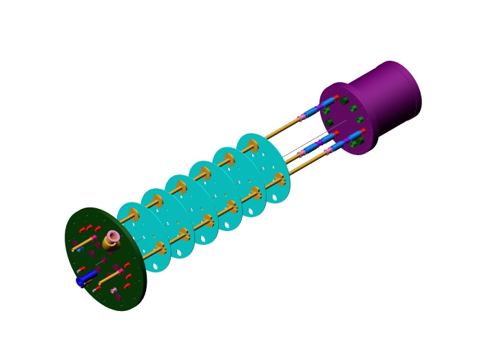
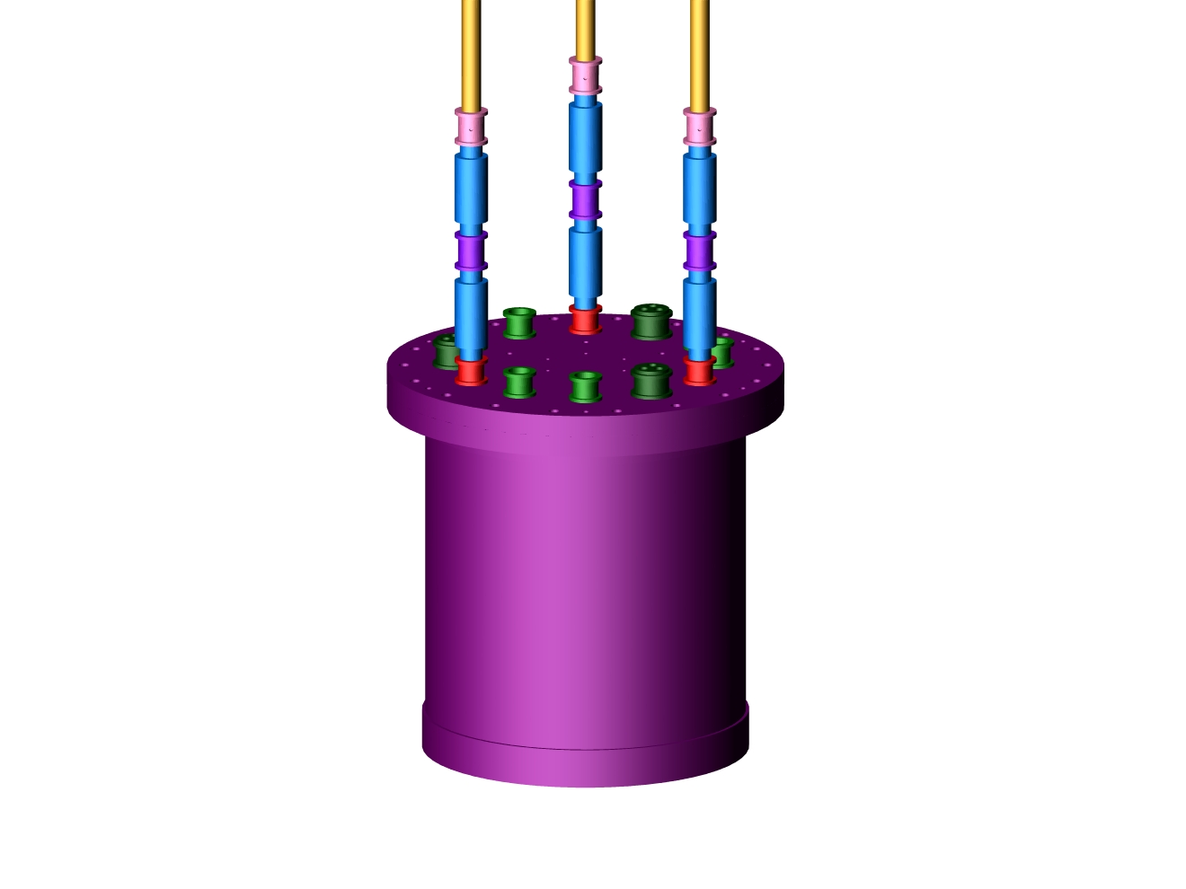
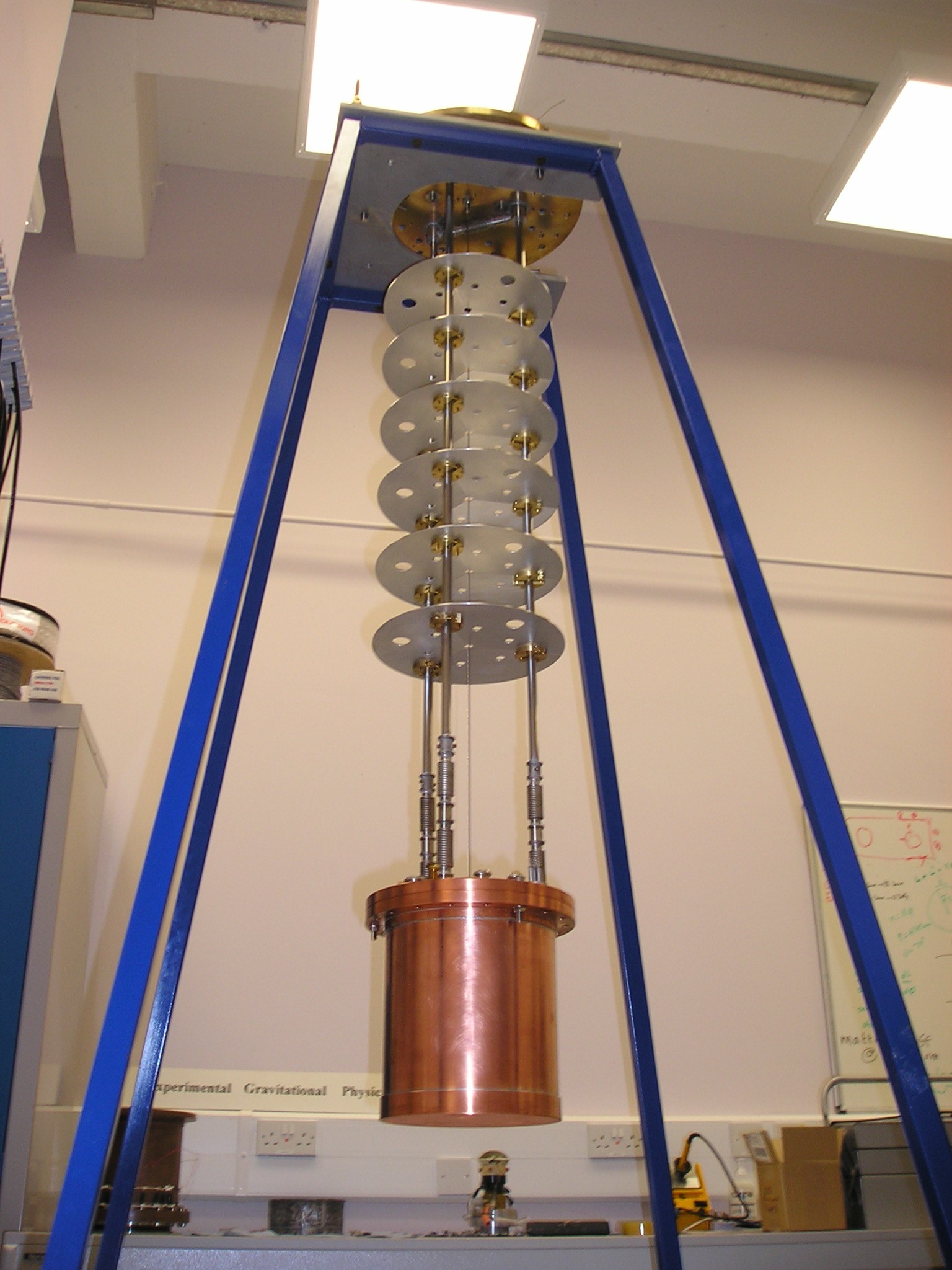
Operation of the experiment at liquid helium temperatures (4.2K) requires the use of a liquid helium Dewar and cryostat insert. We will initially use a Janis research 30 litre Vapour Shielded Dewar. The insert, which is shown in figures 2a and 2b, comprises a brass top plate into which vacuum ports and wiring ports are connected. Three thin walled stainless steel tubes support a copper vacuum can in which the experiment is located. Baffles are also utilised to minimise losses due to convection currents and direct radiative transfer. As the requirements for minimising thermal heat leak and mechanical rigidity are in opposition, thin walled tubes and a massive vacuum can would produce an insert with a relatively low frequency pendulum mode. As a result we have decoupled the vacuum can with a set of bellows. When the insert is lowered into the Dewar it will sit on three contacts that are attached to the base of the Dewar. Thus the tubes will no longer define the mechanical rigidity.
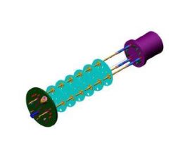
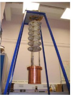
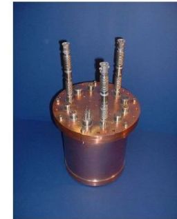
[Figure 2.(a) Schematic/Photograph of the cryostat insert showing the brass plate, baffles and vacuum can. (b) Close-up of the can showing the bellow]
Piezo Manipulator and Cryogenic Interferometer
Although the rotation detector provides a mean of interrogating the output of the torsion balance, its main function will be to apply a restoring stiffness to the instrument and provide a means of applying torques onto the float for the purpose of servo control. We propose to readout the position of the torsion balance with an interferometer working at liquid helium temperatures. One of the main motivations for using an interferometer is to minimise the possibility of magnetic coupling between the SQUID magnetometer and, for example, the levitation field of the bearing. We are currently working on the construction of a cryogenic interferometer that utilises polarisation techniques to provide a continuous, and unambiguous, displacement measurement.
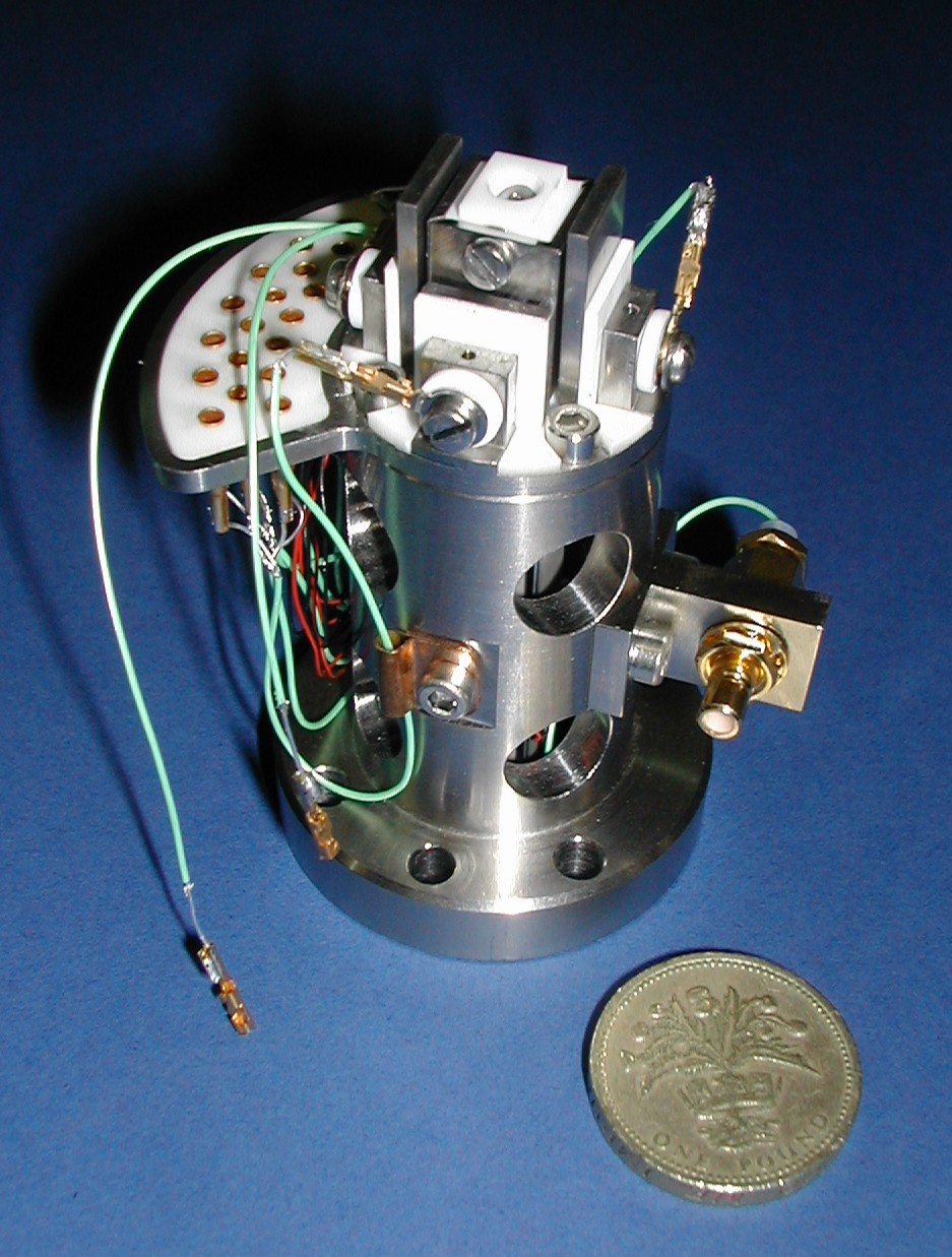
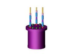
The geometry that will be adopted in the Birmingham experiment comprises a plane attached to the levitated float and a sphere (part of a spherical lens) attached to a 3-axis piezo manipulator. Both surfaces will initially be coated with thermally evaporated gold. We will utilise the piezo to position the spherical source mass and allow scans across the surface of the plane for the purpose of characterising any difference in the properties of the metal film. The piezo has been designed to have a motion in the three axes x,y,z (shown in figure 3) of ±50mm, ±10mm, ±50mm respectively at 4.2K. We still need to calibrate the output of the piezo with the interferometer to verify this. The piezo includes a capacitive sensor on the x and z axes for the purpose of reading out the position of the sphere during operation of the experiment.
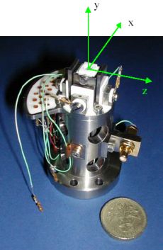
[Figure 3. Photograph of the Piezo manipulator]
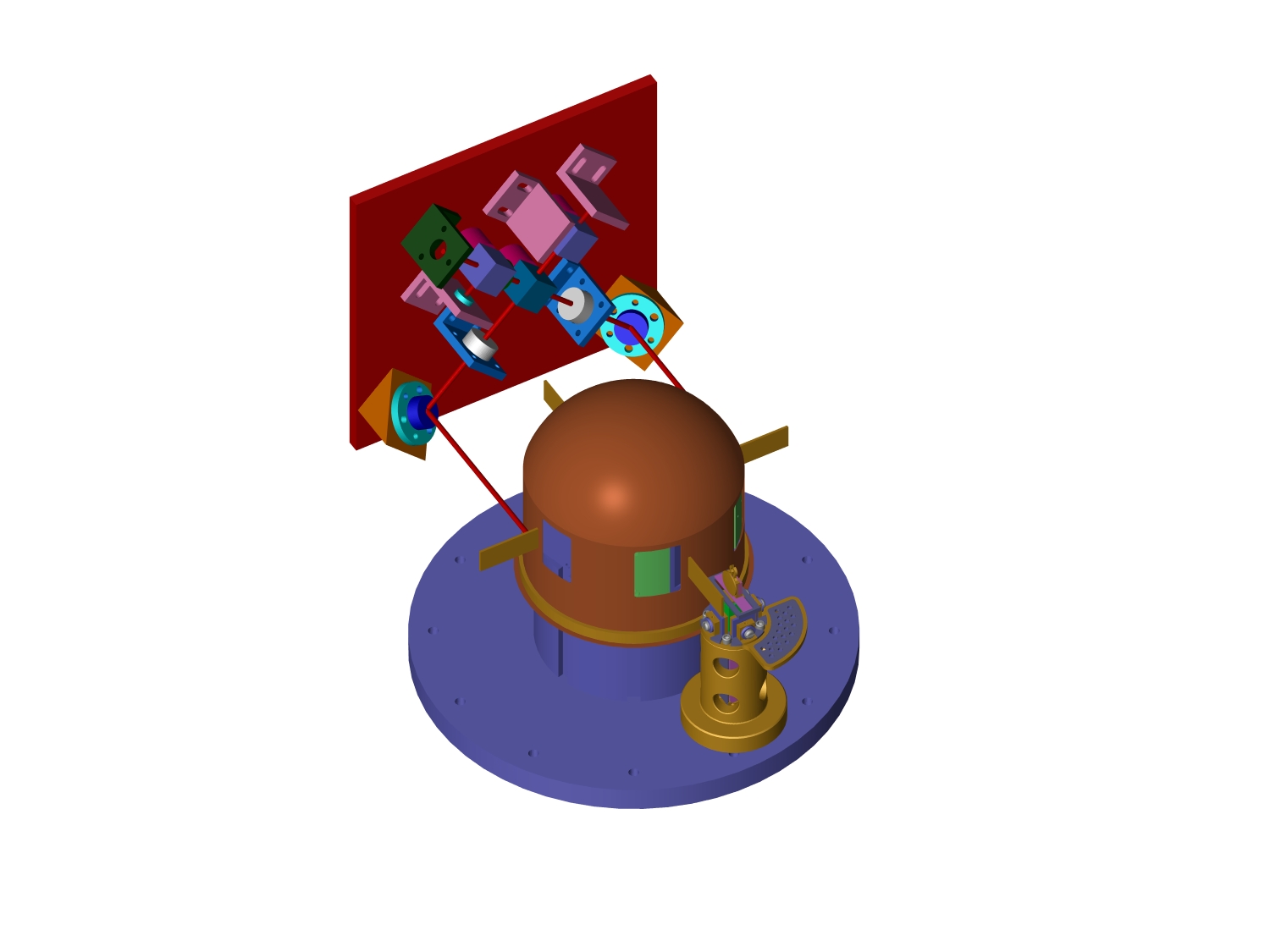
Figure 4 shows a schematic of the whole experiment. The float is shown sitting on the pedestal that houses the levitation bearing. The pedestal will be fabricated from copper and will be used to heatsink charging transformers and heatswitches (for the purpose of storing persistent superconducting currents). The float includes four planar test masses. Two of these will be used for the Casimir sources. The two remaining masses will be dielectric mirrors that will be used to sense the angular motion of the torsion balance. The interferometer will be housed on a block and the two paths will be folded as shown in the figure. The piezo manipulator can also be seen facing one of the Casimir sources. It will be possible to rotate the float by 1800 in order to utilise the second test mass if required. The whole experiment will be located in the copper vacuum can shown in figure 2.
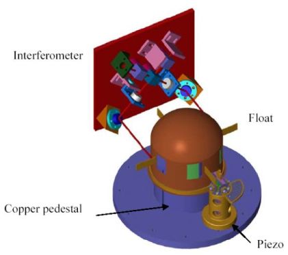
[Figure 4. Schematic of the experimental setup]
References
(1) H.B.G Casimir, Proc. Kon. Nederl. Akad. Wet., 51, (1948), 793
(2) P.W. Milonni, Phys. Rev. A, 38, (1988), 1621
(3) M. Bordag, U. Mohideen, V.M. Mostepanenko, Phys. Rep., 353, (2001), 1
(4) S.K. Lamoreaux, Phys. Rev. Lett., 78, (1997), 5
(5) U. Mohideen, A. Roy, Phys. Rev. Lett., 81, (1998), 4549
(6) B.W. Harris, F. Chen, U. Mohideen, Phys. Rev. A, 62, (2000), 052109
(7) R.S. Decca, D. Lopez, E. Fishbach, D.E. Krause, Phys. Rev. Lett., 91, (2003), 050402
(8) T. Ederth, Phys. Rev. A, 62, (2000), 062104
(9) A. Lambrecht and S. Reynaud, The European Physical Journal, 8, (2000), 318