![[Solar-B]](solarb_ther1_big.gif)
Introduction
After launch, the environment for a scientific space instrument such as EIS is mechanically benign. It will simply be floating in space, attached to the satellite Solar-B. However, the thermal environment is far from agreeable.
EIS will be observing the Sun. This means that EIS will have a significant amount of solar power incident on its front surface. The back, side and top surfaces of EIS will be viewing deep space, which is very cold (-270¯C). So these surfaces will radiate power from EIS into space. The end effect will be a cold telescope with a very hot front end. You may have noticed a similar effect on a still, sunny winter's day: looking up at the Sun, your face is warmed while the rest of you still cold.
Thermal Design Requirements
As EIS is essentially an optical bench, the distances between components such as the mirror and grating are carefully calibrated before launch. The CFRP material and structural design are relied on to keep these distances accurate during launch. Then, despite the low CTE (Coefficient of Thermal Expansion) of CFRP, the temperature difference along the 3.5m length must not be greater than 5¯C. If the gradient does exceed this limit, the optical bench will distort too much to allow images, of satisfactory quality, to be taken. This is where the thermal design comes in. The design of EIS has to incorporate features that control its temperature to the required levels.
A more stringent requirement, on the thermal design, is on the round orbit transient temperature gradient. Every part of the EIS optical bench, including components, must not vary in relation to any another part by more than 0.5¯C. For example, consider an initial situation when the mirror is at 10¯C and the grating is at 13¯C. This satisfies the È5¯C gradient requirement. As Solar-B travels round its orbit, the grating, being at the front of EIS, may cool to 8¯C as Solar-B passes into eclipse from the Sun, behind the Earth. If the mirror does not change temperature, this still satisfies the 5¯ gradient requirement, but the difference between the mirror and grating temperatures has increased from 3¯ to 5¯. It is this change in gradient which must not be greater than 0.5¯, so in this case, the thermal design would have failed to meet the requirement.
Other requirements imposed on the EIS thermal design include the allowable temperature limits for each component. For example:
Thermal Analysis
To predict the thermal performance of EIS when it is in orbit a thermal model was created and analysed using space industry software Thermica and ESATAN respectively. This model represents EIS geometrically in the space environment. Figure 1 shows the complete thermal model of EIS on the spacecraft, while Figure 2 shows a inside view of the EIS thermal model. The thermal model consists of approximately 150 thermal nodes, 100 conductive links and 1000 radiative links.
![[Solar-B]](solarb_ther2_big.gif)
Thermal Design
Figures 3 and 4 are photographs showing EIS thermal design features. Figure 3 is a photograph of the EIS engineering model being prepared for thermal tests. It is a view taken from behind EIS, looking down the mirror tube section, and shows several of the thermal design features. Figure 4 is a view of the top of EIS. It shows the CCD radiator being integrated with the EIS structure.
![[Solar-B]](solarb_ther3_map.jpg)
![[Solar-B]](solarb_ther4_map.jpg)
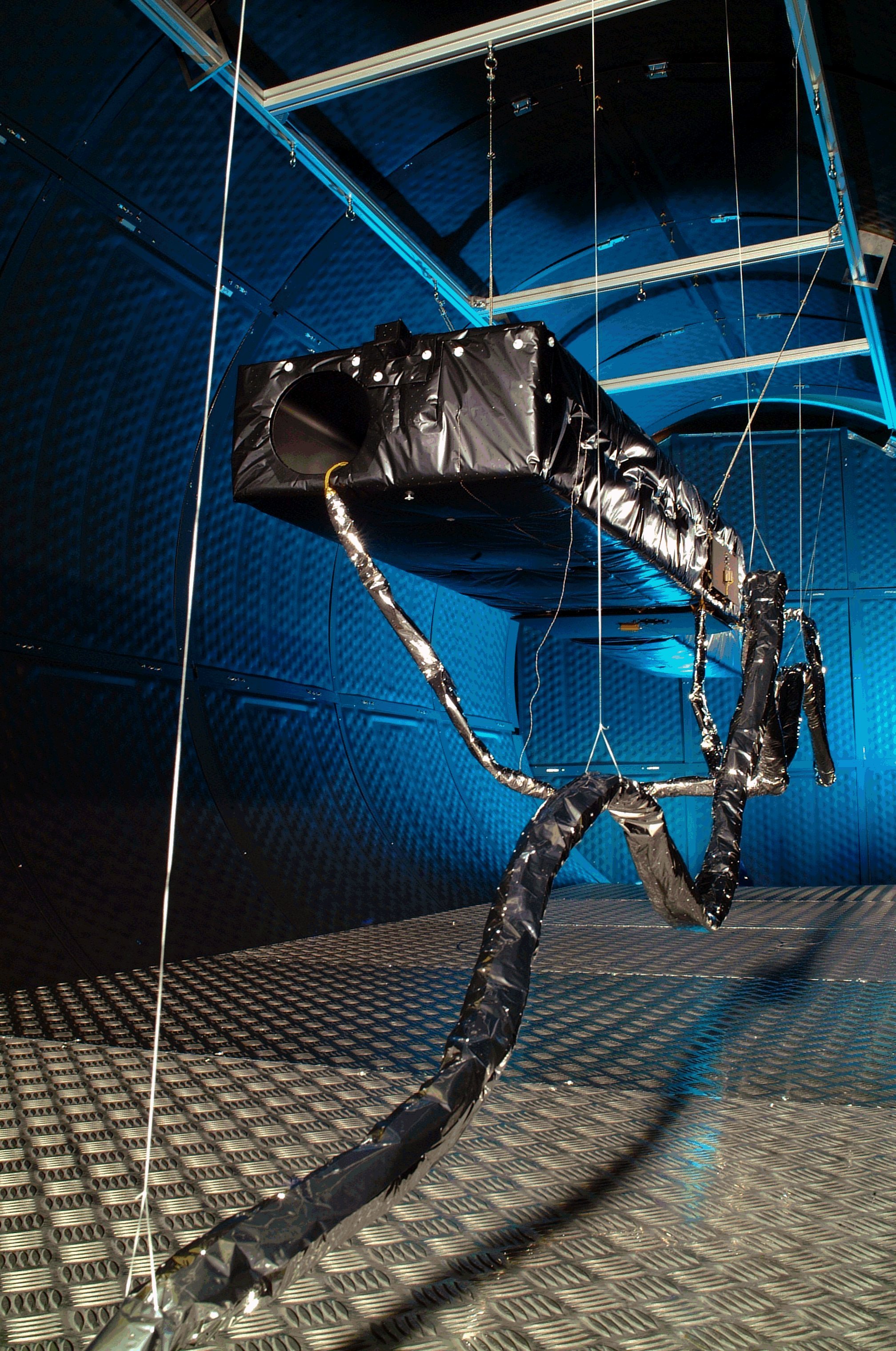
Engineering Model Thermal Balance Tests
The in orbit temperature of EIS was predicted by the thermal model, but the accuracy of this model had to be verified during the engineering model program. The performance of the MLI (Multi-Layer Insulation) also had to be quantified. The EIS engineering model was assembled with flight-like MLI, at the Rutherford Appleton Laboratory. It was tested in their Space Test Chamber. See here for a photograph of EIS in the chamber, prior to testing. The aim was to simulate the temperatures predicted for hot and cold operational in-orbit cases. This was done by cooling a shroud around the inside of the chamber, all around EIS to ~-90¯C, then applying the appropriate power predicted from external sources. EIS was allowed to reach equilibrium and the results compared to those predicted by the thermal model. The thermal model was slightly adjusted, to take into account factors such as the measured MLI performance, and successfully shown to predict EIS temperatures. This has been further verified with the successful completion of the integrated spacecraft thermal balance test.