

![]() How are materials used in structural design?
How are materials used in structural design?
![]()
![]()
This is a very big subject and one in which we obviously cannot go very far here. In addition there are many different considerations that have to be taken into account. It is also a very diverse subject; one can get some idea simply by looking at how nature designs a wide variety of structures (as well as getting them to repair and reproduce themselves).

The Humber, New Tacoma and Golden Gate Bridges - suspension bridges are supported only by thick metal wires, however, the design is such that the bridge is very robust. Sometimes engineers get the design wrong as can be seen in the two movies below of Tacoma Narrows suspension bridge.
In very general terms (but not always true) structures need to be strong and stiff for as little mass as possible. Hence one way of looking at the design of a structure is to consider it as being made as solid and then removing as much of the mass as possible commensurate with the required internal space, adequate stiffness and sufficient strength. This immediately introduces the concept of the arch (in traditional structures) or the beam (in modern structures). These are devices for channelling vertical forces (such as weight) into non-vertical stresses which are carried in the material of the structure. Hence arches channel the stresses to columns in supporting the enormous weights of stone in a cathedral, or a beam spans a river to allow people to cross over without interrupting the flow of water. Arches essentially act under compression and are kept in place by their own mass and hence need to be strong. Beams require to be stiff (though again exceptions can always be found). Both devices are used extensively in our every day lives. In space however, structures acting in compression only are not really necessary because orbiting structures are weightless. Beams are therefore far more important in designing space structures so we shall see how the beam works.
How does a beam work?
If we take a horizontal beam and support it at both ends it will sag or bend under its own weight. If we get someone to stand on it it will bend more. The beam has to bend in order to transfer the vertical force of the weight along the beam to the supports.
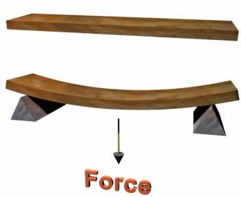
Two beams; the first has no force acting on it whereas the second one has a force acting through the centre.
Comparing the bent beam with the unbent beam we see that the middle part of the beam is essentially unchanged (dotted line), but the upper part of the beam has been shortened and the lower part lengthened. Hence the top of the beam is under compression and the lower part under tension. Both parts are being stressed and are strained as a result.
Increasing the length of the beam (for a given load) causes greater deflection. Decreasing the thickness of the beam (for a given load) also increases the deflection. In both cases the beam is placed under increased stress and ultimately the beam can break (it tends to fracture on the bottom surface and/or buckle on the top surface). Hence we can control the stiffness of the beam through the choice of length and thickness, and obviously, also through the width of the beam. Choosing a material with a large Young's modulus also makes the beam stiffer.
However, by increasing these geometric sizes we are also increasing the weight of the beam which causes it to be stressed further. A way round this is to recognise that the middle of the beam is not greatly stressed and therefore is not doing much work, so why not get rid of it by hollowing out the beam? This is exactly what is done to a greater or lesser extent with beams of different cross sectional designs.
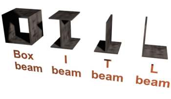
Four designs for the cross section of a beam
Because the box beam is symmetric it is equally stiff in both directions. If we wanted a component which had the same stiffness in one direction only, essentially we want a box beam with say the sides removed. However we still need to keep the two remaining sides separated. This could be done by filling the gap with a very lightweight honeycomb.
This is the basis of the honeycomb panel or composite.
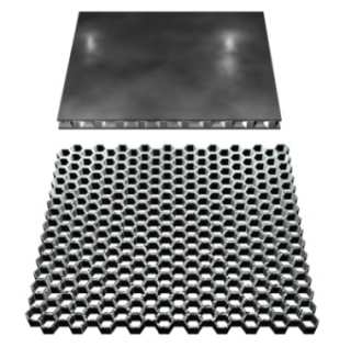
The first picture shows a honeycomb panel with the top and bottom skins attached. The second picture shows the honeycomb interior.
The panel comprises two skins bonded to the honeycomb so that the geometry remains stable. Reasonably strong panels are made with aluminium skins and aluminium honeycomb. Stronger panels use carbon fibre skins. It is interesting to note that some modern domestic doors use wood skins and card honeycomb, so be careful when you saw into one!
Returning to the box beam we could make some mass savings without compromising strength and stiffness significantly by having a series of struts and ties.
A typical design for a lattice strut
Such a configuration is called lattice truss. These are used in such structures as bridges and cranes.
Fabrication or solid ?
If we were to manufacture a lattice truss we could either fabricate it by making the various parts separately and then assembling then or we could attempt to machine the complete truss out of solid. We also have a choice as to how the component parts are assembled; they could be bolted or they could be welded. In the main, a machined system would be stronger and stiffer mass for mass, but usually much more difficult and expensive to manufacture. A bolted assembly would not be as stiff and the holes through which the bolts pass could represent areas of weakness because of the high stresses induced into metal at edges and corners. Welding involves heat treatment with the risk of introducing internal stress which could result in later deformation. Usually any "worked" bit of metal causes in-built stress simply because the process is interfering and reorganising the bonds between the atoms which can store energy. It is usual for ground based structures to be fabricated. For space structures it is not so straight forward because of the trade-off with mass.
What kinds of structures are used in space?
Space structures have to be strong to survive launch where they are "heavy", and stiff to retain their required shape in orbit where they are weightless. Because for every kilogram of payload you need n kilograms of rocket fuel, which also has to be lifted off the ground, mass is a premium. Mass is always a contentious issue and represents a fierce battleground. Space structures therefore tend to be 'open plan' (trusses), make use of composites (lightweight), and/or make use of materials which have high ultimate strength but not correspondingly massive (titanium, glass fibre, carbon fibre etc). Designs are often innovative and work rather close to their limits. However the design has to be very thoroughly verified by testing the hardware before it is accepted for flight.
What kinds of structures are used in XMM?
There are many different kinds of structures and sub-structures on XXM.
Basically, however, XMM is big with the majority of the mass located at the two ends of the telescope.
Because it is big, efficient use has to be made of the mass available. Hence the large panels used to support most of the instrumentation, the electronics and the service equipment are mainly carbon fibre honeycomb panels.
The structure used to support and separate the two essential components of the telescope (the mirrors and the detectors) is a carbon fibre tube. A tube is a variation of a box beam which is equally stiff in all radial directions. A closed structure was required for XMM because it was necessary to keep out the stray light and to keep all the sensitive components clean from contamination. A thin-walled tube or cylinder is a very effective way of achieving a stiff structure for minimum mass.